More Guides
Guide to connect BTT Mini 12864 to SKR Mini E3 V3
Gotten a screen from BIGTREETECH but realized it wasn’t really compatible with the SKR Mini E3 V3? We are in the same position! As SKR Mini E3 V3 does not have EXP3 port and BTT Mini 12864 only have EXP1 & EXP2, both screen is not really directly compatible. However thanks to radek8, we managed to get it work by rewiring the cable from EXP1 + Neopixel to EXP2 and EXP3.

Prerequisites
To get started, you must be ready with
- SKR Mini E3 V3 Board (V1.2 and V2.0 has different pinout)
- BTT Mini 12864
- 12 Pin Dupont Wires 20cm or more (Female to Female)
- Download BIGTREETECH Marlin Firmware as ZIP (SKR-mini-E3-V3.0-G0B1 Branch)
- (Optional) Hot Glue Gun or Tape
Before you begin
Do take note that this require a certain technicial skill with 3D printers and hardware. If you don’t feel comfortable of doing this, do buy the compatible screen such BTT TFT35 or use Stock CR10 Display.
If you are new and feel challenged, feel free to read more about how to compile
Guides: https://www.youtube.com/watch?v=Vn5rMdJgkAI
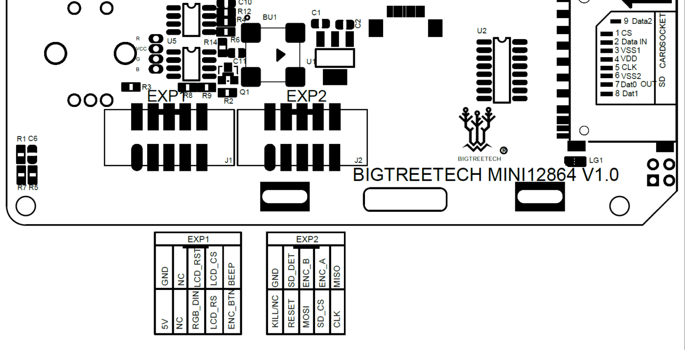
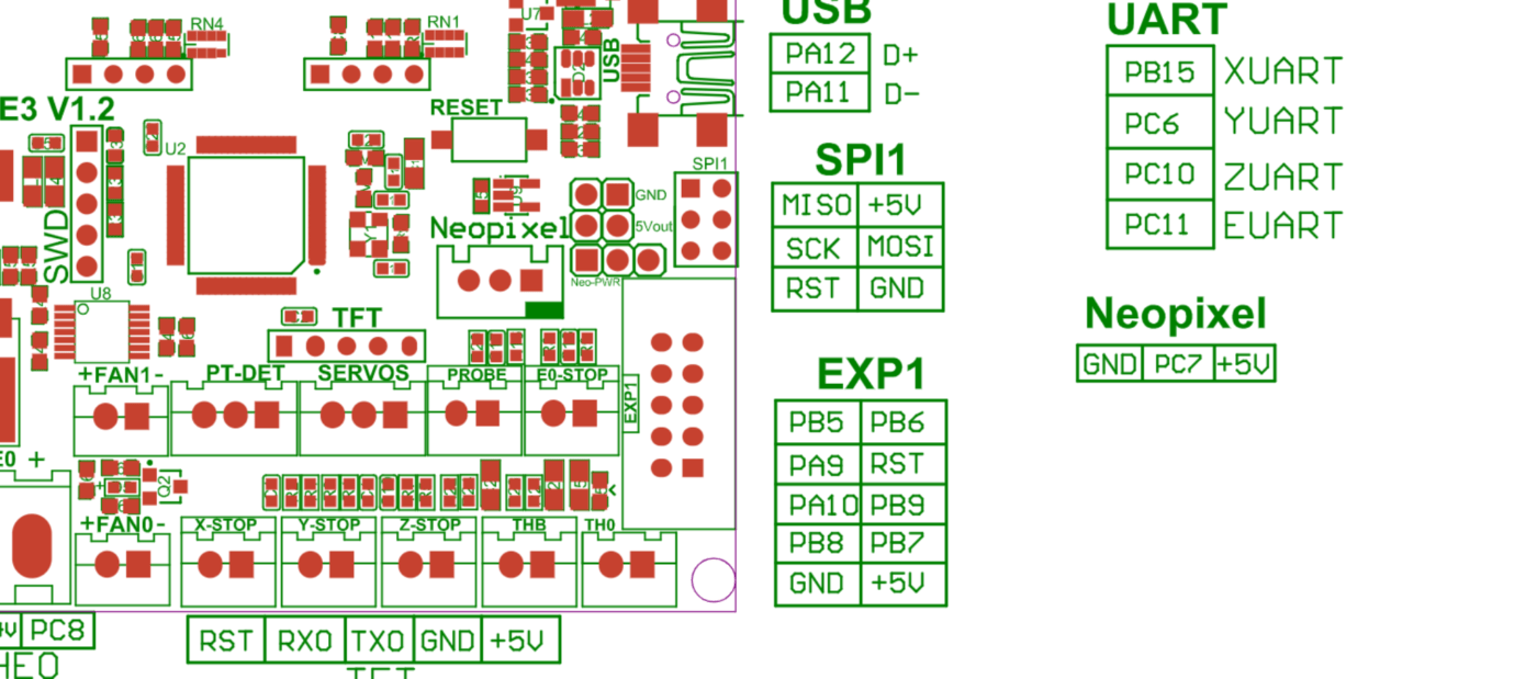
Check out the Pinout
Before proceed further, do take a look at the pinout so in case if you missed out or plugged wrongly, you may know where you been making mistake.


Connect Dupont Wires from Board to Screen

There are two RESET pin, but I’ve only connected to the EXP1 Pin 5
On BTT boards pins from IDC10 connector are numbered in unusual order.
hash tag in the photo above refer to the cable direction.
Compile Firmware with the following options
in Configuration.h, uncomment
#define FYSETC_MINI_12864_2_1
or
#define BTT_MINI_12864_V1
Remember to comment out CR10 Display as each firmware can only allow one.
in Marlin\src\pins\stm32g0\pins_BTT_SKR_MINI_E3_V3_0.h
search for line elif ENABLED(FYSETC_MINI_12864_2_1)
If you can’t find the line above, means the marlin branch may not have the latest code above. copy the following line before #else #error “Only CR10_STOCKDISPLAY…
  elif ENABLED(FYSETC_MINI_12864_2_1)

//#error "CAUTION! FYSETC_MINI_12864_2_1 and clones require wiring modifications. See 'pins_BTT_SKR_MINI_E3_V3_0.h' for details. Comment out this line to continue."

  /**
   *
   *                 Board                               Display
   *                 ------                               ------
   *    (EN2)  PB5  |10  9 | PA15(BTN_ENC)            5V |10  9 | GND
   *  (LCD_CS) PA9  | 8  7 | RST (RESET)              -- | 8  7 | --
   *  (LCD_A0) PA10 |#6  5 | PB9 (EN1)            (DIN)  | 6  5#| (RESET)
   *  (LCD_SCK)PB8  | 4  3 | PD6 (MOSI)         (LCD_A0) | 4  3 | (LCD_CS)
   *            GND | 2  1 | 5V                (BTN_ENC) | 2  1 | --
   *                 ------                               ------
   *                  EXP1                                 EXP1
   *
   *                                                      ------
   *                                                  -- |10  9 | --
   *                   ---                       (RESET) | 8  7 | --
   *                  | 3 |                      (MOSI)  | 6  5#| (EN2)
   *                  | 2 | (DIN)                     -- | 4  3 | (EN1)
   *                  | 1 |                     (LCD_SCK)| 2  1 | --
   *                   ---                                ------
   *                Neopixel                               EXP2
   *
   * Needs custom cable. Connect EN2-EN2, LCD_CS-LCD_CS and so on.
   *
   * Check twice index position!!! (marked as # here)
   * On BTT boards pins from IDC10 connector are numbered in unusual order.
   */
#define BTN_ENC                  EXP1_09_PIN
#define BTN_EN1                         PB9
#define BTN_EN2                         PB5
#define BEEPER_PIN                      -1

#define DOGLCD_CS                       PA9
#define DOGLCD_A0                       PA10
#define DOGLCD_SCK                      PB8
#define DOGLCD_MOSI                     PD6

#define FORCE_SOFT_SPI
#define LCD_BACKLIGHT_PIN               -1
If you copied or found it, comment outerror "CAUTION! FYSETC_MINI_12864_2_1 and clones require wiring modifications. See 'pins_BTT_SKR_MINI_E3_V3_0.h' for details. Comment out this line to continue."

Enable LED_CONTROL_MENU

In the file: Marlin\src\lcd\dogm\marlinui_DOGM.cpp
change parameter:
void MarlinUI::_set_contrast() { u8g.setContrast(contrast); }
change to:
void MarlinUI::_set_contrast() { u8g.setContrast(255); }

The just build and compile with STM32G0B1RE_btt default_envs. Copy the firmware.bin into the microSD Card and reboot, there you go! the screen should works as intended.
That’s all. If you are not getting display but only light, do try again by flashing the firmware. Please do take note that the guide is compatible with SKR Mini E3 V3. If you are planning to use it with V2 and lower, please refer to their respective pinout.

Thank you Smith3D, this serve to connect a BTT Mini12864 V2.0 to a board BTT SKR mini E3 v3.
It seems bad to me that the factory (BTT) did not make this compatibility of products because they are of the same brand, so they should explain this on the official page of the screen BTTmini12864V2.
Connect the wires from board to screen take some time, in this guide needs to correct: in firmware configuration, when you are writing the line: elif ENABLED(FYSETC_MINI_12864_2_1) you need to write on the line the symbol: # hastag which is missing. Also like others, I had to change the name EXP1_09_PIN to PA15 otherwise it wasn’t let me compile the firmware.
I also found this cable on the Bigtreetech page: https://es.aliexpress.com/item/1005001451518988.html?
Could it be used to connect the board to the screen?
thank you very much for this guide
AFAIK, the cable won’t work unfortunately.
i got help with 4.2.7 board and mini12864 v1.0 help
I’m sorry to say that we don’t have a guide available. However, perhaps you could attempt to install the Ender 3 4.2.7 firmware and see if that resolves the issue?
good afternoon, I have the same problem, only the mks gen l board … have you solved this problem?
sorry, we didn’t test out the mks gen board yet
I have wired everything correctly and done all the necessary firmware changes, but there is an issue with the encoder. I can load up and see the main screen, but when I press the encoder button, nothing happens. I can’t access the main marlin menu to be able to run prints and access other things. I don’t think it is the encoder because in the initial screen, if I move the encoder I can change a % value, so I am getting a response. What might be the issue?
I wired the display correctly and made the required change to the firmware, using the exact same hardware but nothing pops up on the display, not even the backlight.
After following the tutorial I was able to get the display to work with the SKR (Marlin bugfix 2.1.x) but only after I hit the reset button on the SKR. Following a reboot the display does not show any characters (it is blank) but the backlights and LED work fine. After I hit the SKR’s reset button the screen comes up as it should. Any idea how to fix this so that I don’t have to hit the reset button after every reboot?
*UPDATE* Today I discovered that is power is applied from an off start of 20 seconds, or longer, the screen will remain blank and not boot. But if I quickly (less than 20 seconds) cycle power the screen will boot properly. Does this help? Any idea what is going on here?
Thanks for the work, it saved me a lot of Time! Now I think about to use the USB Reade which comes with the Display. I found a topic at RepRap.org wher somebody tried its best and was successful (at least he claimed that he was succsessful). I did the same yesterday, but still have some issus.
Unfortunatey I have no idea from deep programming, I just “copy” tutorials like this one. So I´m not able to do troubleshooting by myself.
Smith 3d, do you want to do another tutorial about using the SD Reader in teh display? 😉
the sd card on the display will not work because the cable wasn’t connected to the board. do you have the link to the RepRap?
Why can’t this be done with the SPI EXT 3 adapter board used by the Vorons? Is there a way to get the SD card to work on the LCD?
Anyone knows why my display is on but doesn’t show anything?
I also had to change EXP1_09_PIN to PA15.
My display is BTT MINI 12864 V1.0 and my board BTT SKR MINI E3 V3.0
either wrong firmware or pin wrongly. you don’t have to change the PIN unless needed in code.
It works! Just wrong wiring. Thanks a lot for tutorial!
Anyone knows why my display is on but doesn’t show anything?
I also had to change EXP1_09_PIN to PA15.
Hey there, Great guide! I followed all the steps but my screen looks like it had the contrast to the max… I can’t see anything. I tried to change u8g.setContrast(contrast); to different values (0-128-255), but still no luck. Any thought? Thank you!
Hi… I have followed all the steps, but still getting compilation errors as follows:
DOGLCD_CS’ was not declared in this scope; did you mean ‘DOGLCD_SCK’?
DOGLCD_A0′ was not declared in this scope; did you mean ‘DOGLCD’?
Can you please tell me any solution for this ?
I think you might be declared the wrong parameter. try search DOGLCD_CS and replace them with DOGLCD_SCK. same goes to the A0
Hi, first of all i want to thank you for the hard work and all. I’ve done everything as mentioned, but i had to change the name EXP1_09_PIN to PA15 otherwise it wasn’t let me compile the firmware and now it works. i don’t know if it has an impact somewhere. My main question is first i can’t print from the sd port on my board it shows the insert but next init failed so i try to print from the sd port from my display but there is no response at all. I hope you still read this and maybe can help me to find a way to get it working everything else works as intended. with best regards.
The display SD card won’t work. Seems like your board having issue with the SD Card or can try another with another new freshly formatted FAT32 Card. Either Slot is broken or SD Card issue. The firmware shouldn’t cause SD card Init Fail issue.